
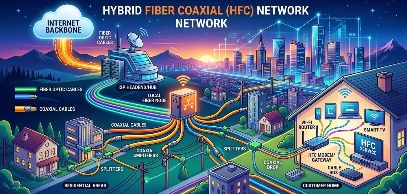
Layer Informatics provide experienced design and drafting services to meet the unique requirements of the cable and telecom industries. Our team has designed and drafted thousands of miles of Hybrid Fiber Coaxial network. At Layer Informatics we prioritize continuous education and training to ensure our team remains up to date with latest advancements and trends in the industry evolving technology. Our design capabilities include experience like:
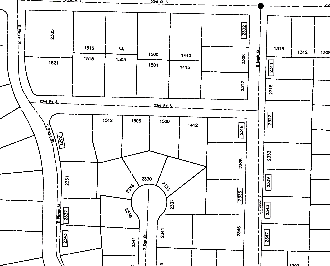
It is the foundational geospatial layer in telecom design. It provides real-world context - such as roads, terrain, parcel boundaries, and physical structures - upon which Fiber, wireless, and outside plant (OSP) networks are engineered. It ensures highly accurate routing, optimal site selection, and regulatory compliance.
In the context of cable television (CATV) and broadband Hybrid Fiber-Coaxial (HFC) networks, a "walk out" refers to a physical site survey or field inspection. Field engineers walk the route of the proposed or existing cable lines to document physical features, verify utility pole clearances, and map out where coaxial amplifiers, taps, and nodes need to be placed.
The "walk out" process in a hybrid coaxial design involves the following core steps:
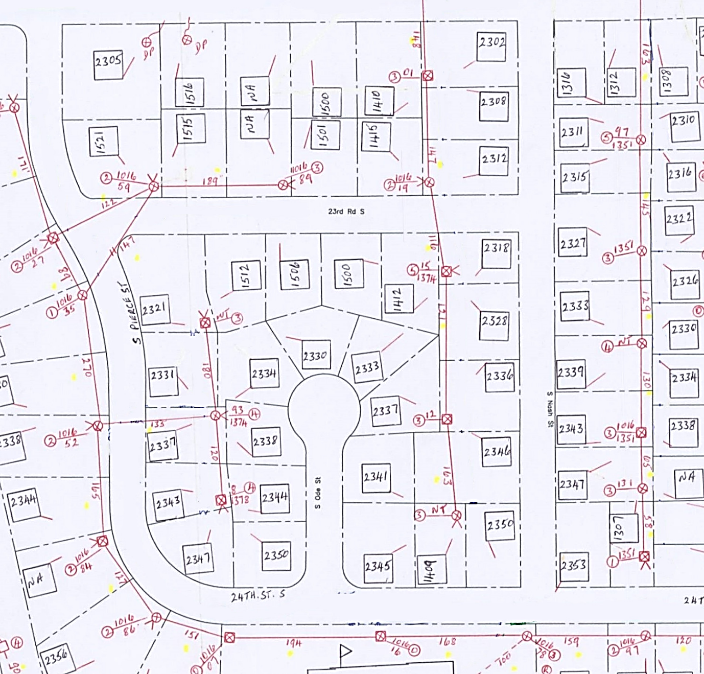
Strand is the supporting infrastructure on which RF and fiber optic cables, along with network equipment, are installed.
Strand mapping and field data capture form the foundation of HFC network design and construction. This process involves converting field walkout information into an accurate digital GIS map in accordance with customer specifications and engineering standards.
For aerial networks, strand is mapped between poles, while for underground (UG) networks, trench routes are mapped between pedestals. Home addresses are also captured to accurately represent RF drop locations and potential serviceability.
Strand mapping includes the accurate Drafting of:
Accurate strand mapping ensures reliable network planning, efficient construction, and up-to-date as-built documentation throughout the HFC network lifecycle.
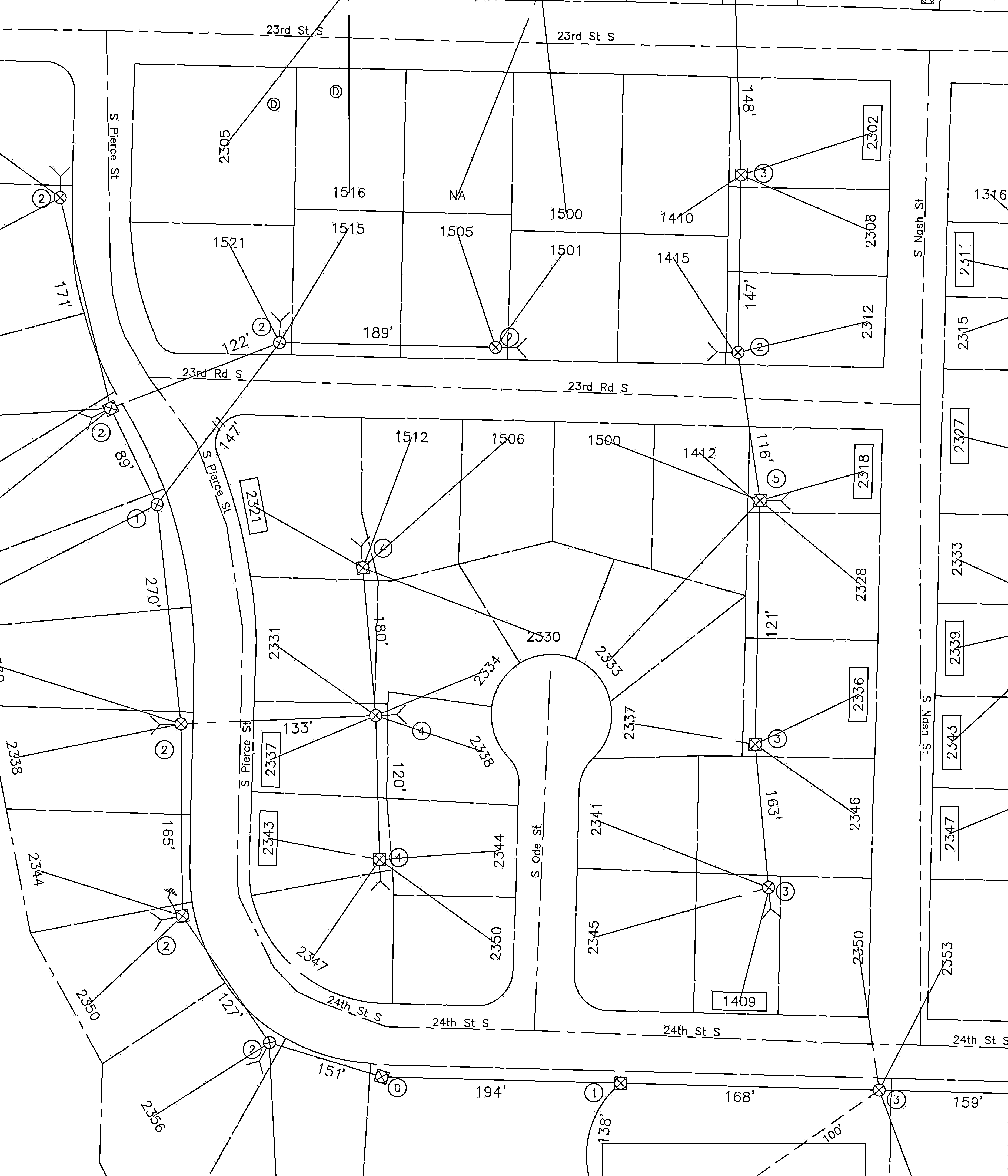
RF Network Design in Hybrid Fiber-Coaxial (HFC) architecture is the process of engineering the coaxial portion of a telecommunications network. It ensures signals travel flawlessly from an optical node to end-user homes. Designers calculate signal loss, balance power, and position amplifiers and taps to maintain optimal bandwidth.
Upstream vs. Downstream Balancing: HFC design must handle two-way communication. Downstream signals travel from the node to the home, while upstream signals (like uploading data) travel from the home to the node.
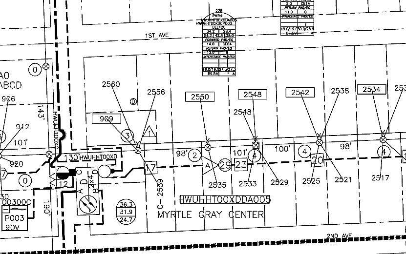
The scope of work includes the planning, design, and documentation of fiber infrastructure within the HFC (Hybrid Fiber-Coaxial) network to support network expansion, node segmentation, capacity upgrades, and service reliability improvements. This involves designing fiber routes from the hub/headend to optical nodes, assigning fiber strands, developing splice plans, and ensuring compliance with customer engineering standards and specifications.
The work also includes preparing detailed engineering deliverables such as fiber route maps, splice schematics, fiber assignment sheets, optical loss calculations, and construction drawings. All designs will be reviewed for accuracy, continuity, capacity requirements, and future scalability to support current and future network demands.
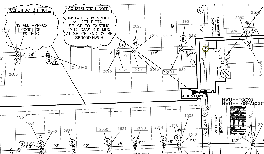
FTTx (Fiber to the x) design for EPON (Ethernet Passive Optical Network) and GEPON (Gigabit EPON) involves planning a point-to-multipoint fiber-optic network where unpowered optical splitters route data from a Central Office to end users. The design strictly dictates the layout of fiber cables, splitters, power budgets, and equipment for data, voice, and video delivery.
The design is also prepared in matrix form using CAD software as a CAD Matrix, which represents the internal connectivity in a graphical format and helps in easy understanding and field construction support.
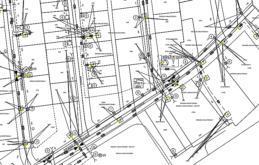
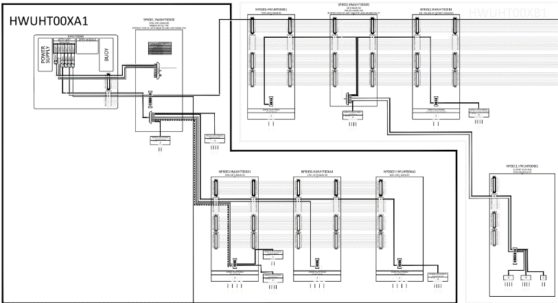
Node Split Design (also known as a node segmentation or node cut) is a network optimization strategy used by telecommunications companies to increase bandwidth capacity. It involves dividing a single, overloaded optical node into two or more smaller nodes without digging up new streets to lay main fiber lines.
Cascade Reduction: Cable networks use amplifiers to boost signals over long distances. Node splits naturally reduce the "amplifier cascade" (the number of amplifiers lined up in a row), which drastically lowers RF noise and improves signal quality.
Stepping Stone to FTTH: It pushes fiber closer to the subscriber, making a future transition to pure Fiber-to-the-Home (FTTH) much easier and cheaper.
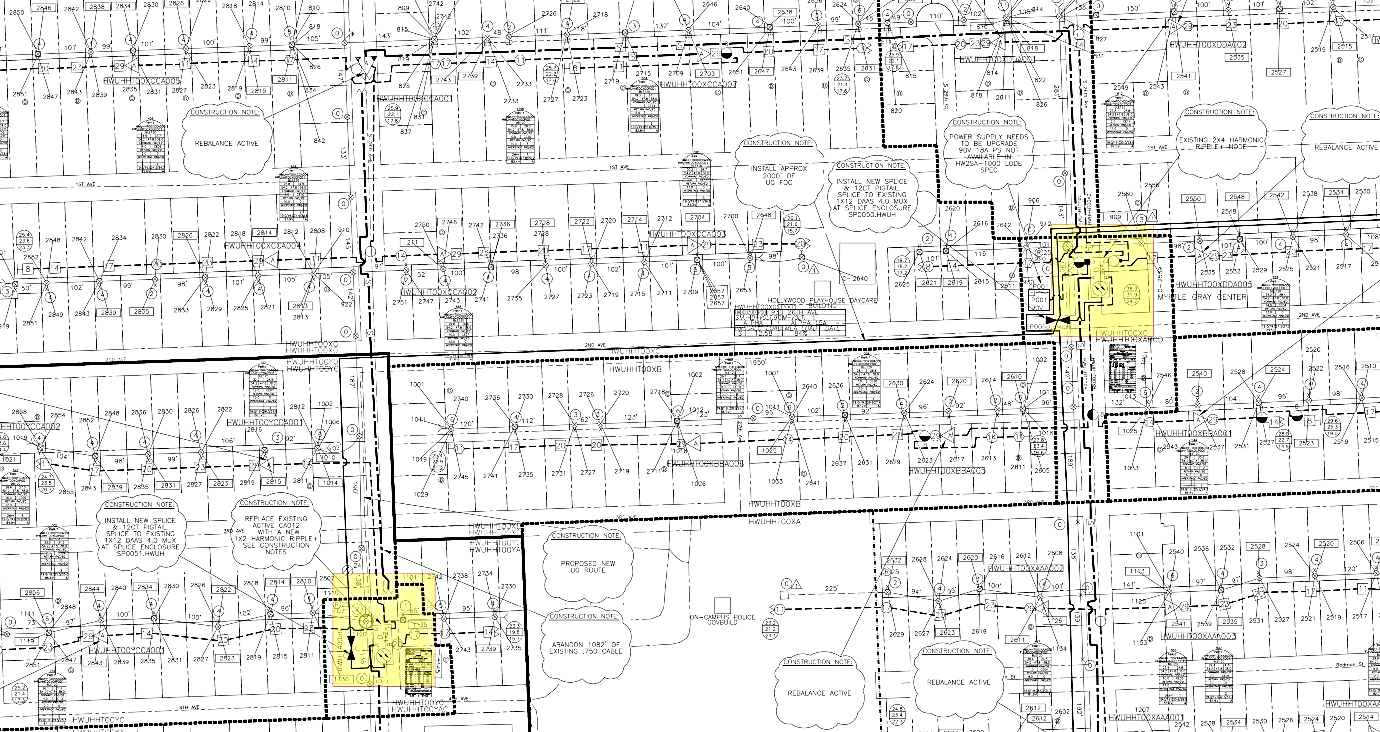
Engineering drafting in telecom design translates conceptual network architecture into precise, permit-ready construction drawings (CDs). It provides field and installation crews with exact physical and logical blueprints for deploying wireless infrastructure (like 4G/5G towers and small cells) or wired networks (like Fiber-to-the-Home or FTTx).
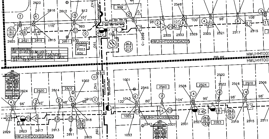
The As-Built Design process is performed after construction activities are completed. The construction team provides marked-up design maps and supporting documentation reflecting the actual field conditions, including any deviations from the original approved design. The scope of work includes reviewing the construction redlines, validating the changes, and updating the design records to accurately represent the network as constructed.
This work involves incorporating field modifications such as route changes, cable placements, splice updates, equipment relocations, and other construction-related revisions into the design maps and associated documentation. The final As-Built deliverables provide an accurate representation of the network infrastructure, ensuring that engineering records match the installed facilities and support future operations, maintenance, and network planning activities.
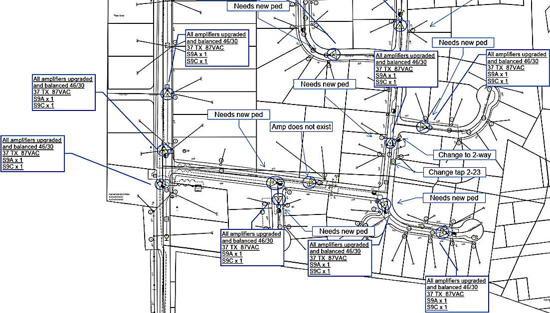
Addressing in telecom network design dictates how devices, subscribers, and services are identified, routed, and managed. It blends hierarchical IP spaces (IPv4/IPv6), telecom-specific numbering (MSISDN, IMSI), and physical MAC identifiers to ensure scalable, secure, and globally interconnected communication systems.
Data migration in telecom design is the critical, highly complex process of moving massive volumes of structured and unstructured data (e.g., subscriber records, billing systems, and CRM databases) from legacy platforms to modern target systems. It requires rigorous ETL design, data cleansing, and strict downtime management.